Understanding the Spanning Tree Protocol (STP)
Posted on 9 February 2018 by Beaming SupportWhat is STP for?
The spanning tree protocol (STP) was introduced into the networking world as a means to prevent layer 2 network loops (frame broadcast storms) from disrupting the service of a local area network. STP uses clever mechanisms to prevent loops by virtually disconnecting redundant links.
If it weren’t for STP, broadcast storms would occur, especially in the topology below.
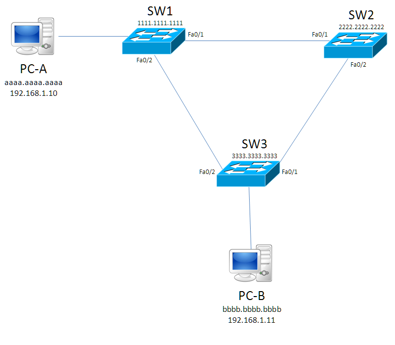
We are to assume that the switches have not yet populated their CAM Tables, and PC-A (192.168.1.10) is trying to send a frame, e.g. a ping, to PC-B (192.168.1.11).
First, PC-A must find out the MAC Address of PC-B. This is done via an ARP request, which has a desintation MAC Address of ffff.ffff.ffff (the Layer 2 Broadcast address). At this point, SW1 will see the frame and forward it out of both its ports to SW2 & SW3. SW2 will forward it to SW3, now SW3 will forward the frame to PC-B (twice), and back to SW1 & SW2. That’s hard to wrap your head around, but what happens here is a loop that will never end, as frames have no TTL data to timeout.
How does Spanning Tree Protocol prevent loops?
STP will attempt to stop redundant links in the switched network from allowing traffic on them, for instance the link between SW2 and SW3 could be considered redundant, because if this didn’t exist they’d still be linked. However, redundancy is a network engineer’s best friend, as it acts as a brilliant failover feature in case another link was to break, so ideally we’d like to keep this redundant link.
Root bridge election
STP has a few things to set up before it can decide what links will be lost. First there is the Root Bridge Election which will elect one of the switches to be the ‘Root Bridge’. The Root Bridge has none of its ports blocked, thus it will not lose a link. In order for this process to happen, all switches act as if they are the root bridge to start off with, and will send Bridge Protocol Data Unit (BPDU) packets every 2 seconds, advertising themselves as the root. So how do they decide which wins and which loses? It’s all done with the Bridge ID (BID) which contains a 2 byte priority field, and the 6 byte MAC address of the switch itself.
Above is an image of this concept, now to understand why this is needed. The priority field has a default value of 32768 which doesn’t change (unless an engineer manually alters this to have a lower value). After this is the MAC address of the switch. The switch with the lowest BID wins the election; this means that if default values are used, the switch with the lowest MAC Address will win the election. Note, if you are configuring the priority section of Cisco switches, you will notice a quirk in that you can only change this value in multiples of 4096; however this means delving into Cisco’s version of STP called PVST+ (Per VLAN Spanning Tree Plus).
In our example diagram, all switches will begin to think that they are the root bridge, so they will originate BPDU frames indicating that they are the root bridge, when SW3 receives a frame from SW1 it will notice that SW1’s BPDU shows a lower Root Bridge ID (Root BID) so it gives up trying to “win” . SW2 will do the same, so SW1 “wins” and will be the root bridge of our little network.
In order to work out which will have their ports blocked, we need to assign port types to the switches.
We’re networking experts
When it comes to private wide area networks and business continuity services, a “set it and leave it” approach just doesn’t cut the mustard.
Calculating port roles
There are three port roles that we are going to address in this blog:
- Root Ports : A root port is a port that has the best path to reach the root switch, of course a root switch has the best path to itself so it will actually have no root ports. Every other switch has only one root port.
- Designated Ports : Since it has no root ports, a root switch will have all its ports set to designated. This type of port isn’t only for root switches; on a non-root switch, once the root port has been established, all other ports become designated ports.
- Blocking Port: In theory this isn’t actually a state, rather a lack of states. When a switch port is neither root nor designated, it will go blocking.
In order to work out which will become the root and designated port, we need to know the Root Port Cost (RPC) of each switch port on a non-root switch. The switch port with the lowest RPC will become the root port, and all of the other ports will become a designated port. So how do we get this value? There are many types of cables and speeds, but we’re going to focus on 4 types that you’re more likely to see in a network.
In the above table, I have assigned the Root Port Cost to the speed of the cabling type. It is very important to note that, even if you are using a GigabitEthernet link/port STP will calculate theRPC based on the speed it is running at. For example, if the link negotiated a speed of 100mbps on a gigabit link, it will choose a cost of 19, not 4.
Here we have altered the diagram slightly to introduce the RPC values. We can see that on W3 F0/2 the cost is 19 because there is a FastEthernet link between SW1-SW3 and we presume it is running at its optimum speed of 100mbps. This cost is lower than SW3 f0/1, which has two FastEthernet links along the line, meaning we have to add together 19+19 making 38. The switch will choose the lowest RPC for its root port so SW3 f0/2 will be the root port.
We now know the root ports for the switches and need to determine the designating and blocking ports. SW1 will have all ports set to designated as no ports will enter blocking mode. All that is left is working out what’s going to happen with the link between SW2-SW3. One will be designated, but the other will have to go blocking; this is because there can only be one designated port on a collision domain, and the root port has already been selected on both switches. To work out which will “win”, and will get the designated port, there are a few tie breakers to work with:
- Switch with the lowest RPC wins
- Switch with the lowest BID wins
- Switchport with the lowest priority value (default is 128 unless changed)
- Switchport with the lowest number e.g. F0/1 would beat F0/2.
With this information, we can quickly work out which will become the designated port, and which will go blocking. First, which has the lowest RPC? Neither of them; each switch’s lowest RPC is 19, so this is a tie. Second, which has the lowest BID? Here the ties end and SW2 wins, so SW2 F0/2 will become designated. SW3’s F0/1 will go into blocking. This basically ends the function of STP, however there is one last concept to cover which is helpful to understand why it takes a long time for STP to converge (reach its final state).
Port states
There are 5 states that STP can be in, explained in the following table
| State Name | Description |
| Disabled | This is a port which has both its physical and logical lines down. In regards to Cisco, this would be a down/down or administratively down interface. |
| Blocking | When a port is neither a root or designated port, it will be in a blocking state so it will not send or receive data (exemption from BPDU frames, as it will actually accept these to keep up to date STP information). |
| Listening | When in a listening state, it will flush all MAC address entries on that interface, and will inform its neighbour to do the same on its interface on the same link. It will then stay in this state for 15 seconds (Forward Delay default time) before moving onto the learning state. |
| Learning | When learning, it will still discard frames, but it will begin to learn the MAC addresses of the devices, it will also stay in this state for 15 seconds. |
| Forwarding | This is the final state, and will take a minimum of 30 seconds when the Forward Delay is default. It will send/receive data and work as normal. |
When something changes to a port, e.g. it is disconnected/reconnected or shutdown/no shutdown STP will recalculate its algorithm to ensure that there are no loops in the network. It will first place the port that changed into blocking mode, which quickly moves into listening mode. It will flush its MAC address table (and its neighbours’) before waiting 15 seconds to move on to learning mode. In this state it will start learning MAC addresses but it will not send/receive data yet, this is achieved after another 15 seconds when it moves into forwarding mode.
The minimum time to reach forwarding state is 30 seconds, with the maximum being 50 seconds. This is because there is a MaxAge timer of 20 seconds; when a switch doesn’t receive a BPDU frame on a blocking port for this long, it will assume that the switch isn’t there, and begin to place the port into forwarding mode, as it would assume that a client is on the other end. So 20 + 15 + 15 = 50 seconds.
This was just a basic overview of the STP algorithm, there are actually two other variants, known as Rapid Spanning Tree Protocol (RSTP) which achieves quicker convergence time (really quick), and there is also Multiple Spanning Tree Protocol (MSTP) which is for load balancing per VLAN in a network.
There are also some extra features such as PortFast and BPDUGuard which are handy tricks to know. PortFast should only be placed on access ports pointing at clients, as this mode will skip the states, so from blocking it would actually go straight to forwarding. This is brilliant for clients as they’ll be on the network quicker. BPDUGuard blocks a port if it receives a BPDU frame from a rogue switch which may attempt to corrupt a network. This port becomes err-disabled and requires a shut / no shut on the specific port to bring it back.
Avoid internet downtime
IT professionals in UK businesses dealt with 82M hours of internet outages last year.
Clients we’ve supported
Our happy customers share the results they’ve achieved with the help of Beaming’s connectivity and related services.
- Leased Lines
- WiFi
- Digital Transformation
- Tricky Location
- Hospitality/Leisure
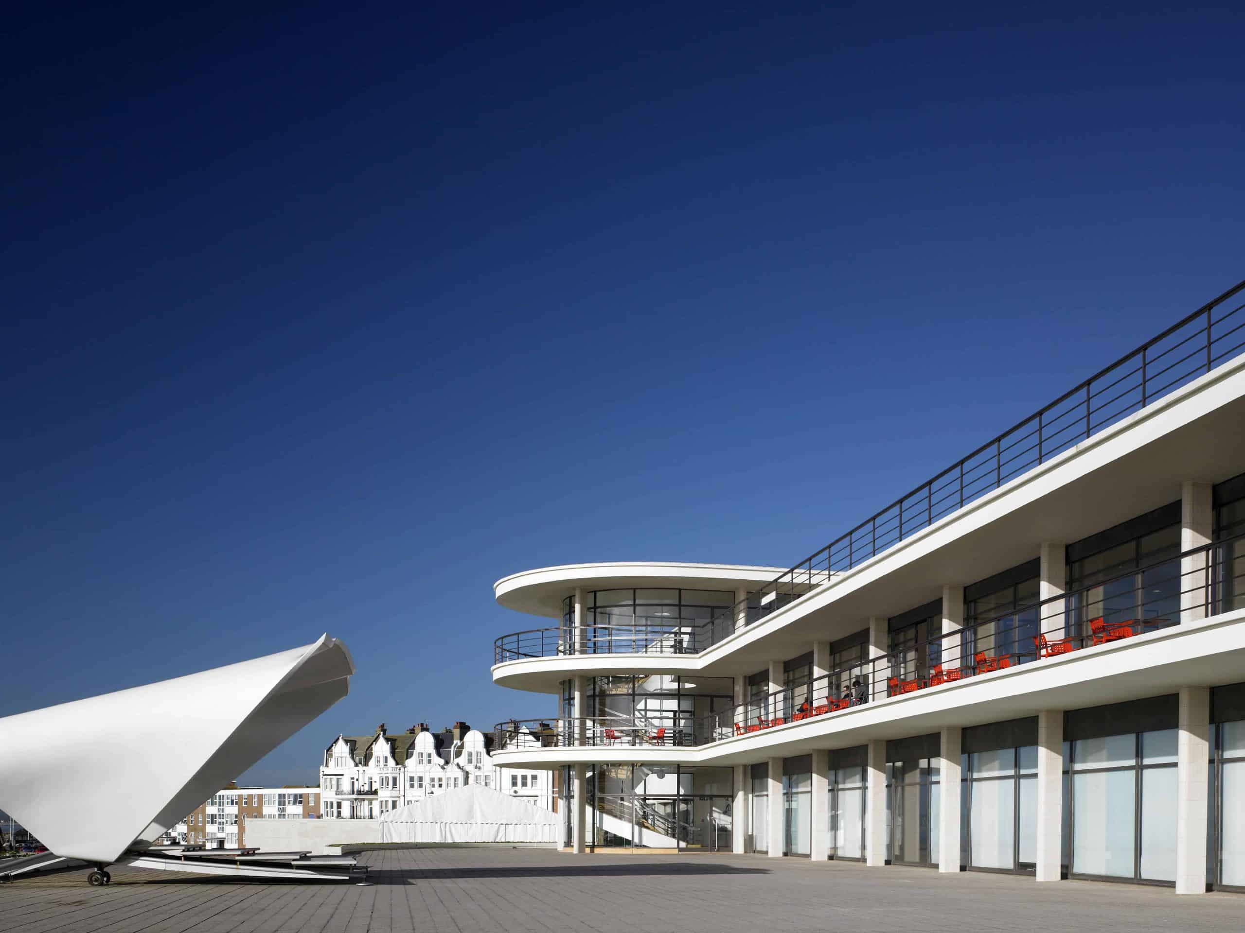
De La Warr Pavilion
‘Est. 1935. Modern ever since’ is the tagline of this cultural centre, but much work was needed to ensure that promise is upheld in our hyperconnected age.
- ProtectNet
- Leased Lines
- Data Security
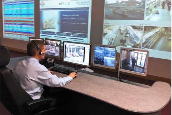
Corps Security
Beaming worked with key security industry players to develop the ProtectNet service. For businesses like Corps Security, it protects their network, and their reputation.

- Education
- Leased Lines
The Sabden Multi Academy Trust
Bringing much-needed synergy to some very special schools

- Leased Lines
- SME
- Tech
Zoonou
When your business is all about the internet, brilliant digital connectivity is less of a helping hand and more of a vital organ. Zoonou needed us – but more than they knew.
- Leased Lines
- WiFi
- Digital Transformation
- Tricky Location
- Hospitality/Leisure
De La Warr Pavilion
‘Est. 1935. Modern ever since’ is the tagline of this cultural centre, but much work was needed to ensure that promise is upheld in our hyperconnected age.
- ProtectNet
- Leased Lines
- Data Security
Corps Security
Beaming worked with key security industry players to develop the ProtectNet service. For businesses like Corps Security, it protects their network, and their reputation.
- Education
- Leased Lines
The Sabden Multi Academy Trust
Bringing much-needed synergy to some very special schools
- Leased Lines
- SME
- Tech
Zoonou
When your business is all about the internet, brilliant digital connectivity is less of a helping hand and more of a vital organ. Zoonou needed us – but more than they knew.