What is a VLAN?
Posted on 7 March 2019 by Beaming SupportWhether you are learning the basics of networking, or you are just curious about how VLANs work, this guide is suited to anyone with beginner knowledge of computing or networking.
Local Area Network (LAN)
A Local Area Network (LAN) is in its simple form an isolated private network (e.g. home, school or office) which is inaccessible from the internet. It shares a single broadcast domain, which in networking terms means it is a network where all connected clients can communicate with one another over local devices.
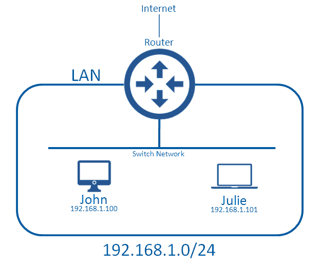
In this diagram, John and Julie can send each other messages without consulting the router; this is because they are within the same broadcast domain (LAN).
What defines the boundaries of the LAN is the Network IP Address (ID), and Subnet Mask. In this network we are using the Network ID 192.168.1.0, which has a subnet mask of /24. We won’t go into subnetting here, but this setup means that anyone with an address of 192.168.1.X,where X is any value, can communicate with one another without a medium device such as a router (which routes traffic from the local network to external networks), they instead communicate over the local network. The device that typically handles this is a switch or a wireless access point.
When a device wants to communicate with a computer outside of the LAN it will need to send all of its data to the router, which will make the decision to forward it on either to the Internet or to another LAN.
This segment can be called a broadcast domain because there is a type of traffic known as broadcast traffic which attempts to send the message to everyone in the local area network. This works because the switch network will forward the message to all devices (including the router) but the router will not forward it to external networks, which is the edge of the broadcast boundaries.
Virtual LAN (VLAN)
What if we have a bigger network, and want to keep the confidential data of a corporate network separate from the public WiFi, used by guests and potentially malicious users? This is where having multiple LANs comes in handy, because we can stop guest users from sending/receiving traffic from the corporate LAN.
There are two main options for this type of deployment: The first is one that uses no VLANs but rather multiple LANs (this may initially sound like the same thing, but we’ll come to that).
Option 1 – Multiple LANs
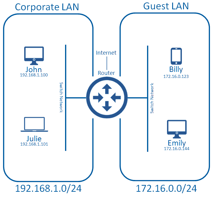
This is a perfectly acceptable deployment method, but you have to have the ports available on your router to do this. Most entry routers (e.g. Cisco 1921) have two Ethernet ports; one would typically be used for connecting to the WAN (service provider, or corporate HO) and another connects to one of the corporate LANs. This unfortunately doesn’t give us a spare port for connecting up the guest LAN. Cisco routers do allow you to attach more Ethernet ports, but this normally comes at a great cost. As the network gets bigger, and we need more LANs, we will need more ports the router. This will get extremely expensive, and eventually the router won’t be able to accept any more Ethernet ports, at which point we get into something of a muddle.
Option 2 – Virtual Lans (VLAN)
Now we get on to the VLAN. A VLAN allows us have multiple LANs, which come off of only one physical port on our router; perfect!
This can only work if you have physical equipment that can handle VLANs and the 802.1q standard for trunking, which we’ll touch on later. Fortunately a lot of consumer grade networking devices come with this by default, as it’s such a widely used protocol.
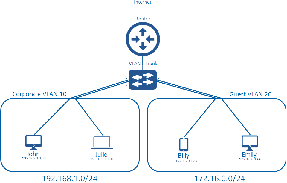
We have added a switch to this diagram, to replace the ‘local network’ part so we can further explain how VLANs truly work. A typical network switch comes with 24 or 48 ports on them (there are many types, with many different densities, but in normal corporate networks you’ll likely see these). Each of these ports connects to clients in the network via an Ethernet cable, which grants them access to the networking medium.
By default, all ports on a switch are in the default VLAN; VLAN 1. When no configuration is applied, this creates a flat network where all clients can communicate with one another, which virtually looks like the first diagram in this blog. Instead of this, you can create multiple VLANs on the switch, and apply them to the switch ports. For instance, we apply VLAN 10 to ports 1 and 2, and apply VLAN 20 to ports 3 and 4.
What this does is separate the broadcast domain, so that when broadcast traffic occurs on VLAN 10, it doesn’t bleed into VLAN 20. It also means John and Julie can communicate with one another, but they cannot communicate with Billy and Emily on the other VLAN.
VLAN tagging and trunking
We have now separated our LANs through the use of Virtual LANs; however they are not yet set up to communicate with the wider world via our Internet connection.
Let’s take a step back and think about the switch ports allocated to a specific VLAN. These are known as access ports and will handle only one VLAN. Users will send their normal traffic through that port and once received by the switch, it will associate that traffic with the VLAN. If the traffic is going to leave the VLAN to the internet (or another network outside of it’s VLAN) it needs to tag that traffic with a VLAN Header so that the Layer 3 Device (Router) is aware how to handle the traffic.
The header is placed within the Layer2 Frame just after the Type field, as shown below.
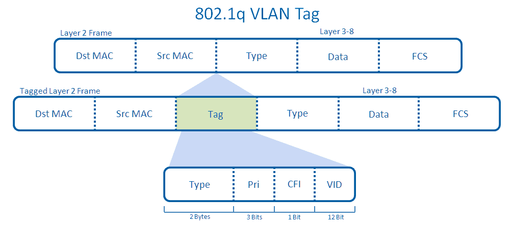
The tagged Layer 2 Frame will then be sent across the trunk between the switch and the router. This port has become a trunk because an administrator has manually configured this uplink to become one. The trunk is able to send traffic from any VLAN by default, though this can be manually restricted.
Let’s say John who is in VLAN 10 wants to navigate to www.beaming.co.uk. He will have to send this data to his switch, which will associate that traffic in VLAN 10, as the administrator has configured his port to be in that VLAN. His Layer 2 traffic will then be tagged with an 802.1q header and sent across the trunk up towards the router. The router at this point will look at his VLAN, and see he’s a part of VLAN 10. The router will associate this traffic with a Switched Virtual Interface (SVI) inside of the router, which might have access lists to control the restrictions on his traffic before forwarding it onto the internet like normal traffic.
One final point is native VLANs; by default this is VLAN 1, and traffic from VLAN 1 sent from the switch to the router is not actually tagged, but the router on the other end (by default) will assume that all untagged traffic is from VLAN 1, unless manually configured otherwise by an administrator.
Was this helpful?
Beaming is an Internet Service Provider for businesses, so when it comes to networking, cyber security and tech, we know our stuff. We share our knowledge in a monthly email update to subscribers. Sign up below.